
|
|
||
|
|
||
|
|
||
|
|
||
|
|
![]()
SWITCHING POWER SUPPLY ADAPTOR FOR DRAGON'S LAIR, SPACE ACE, THAYER'S QUEST
Written by Shaun Wood - 2 May 2013
INTRODUCTION
An original replacement power supply can be difficult to
find. A simple solution is to use a commonly available switching power supply.
You just need to build a small adaptor having the same two Molex connecters
found on the original supply. This document will show you how.
POWER SUPPLY NOTES
The Dragon's Lair / Space Ace system relies on the power supply for three output voltages: +5VDC for logic, +25VDC for audio, and 6.3VAC for coin door lights. Since no switcher supply provides the 6.3AC volts, we will be forced to use +5VDC for the lights. They will be slightly dimmer, but not enough to be a problem.
My tests show that a running Dragon's Lair boardset draws about 600mA on the 5 volt line, and less than 500mA on the 25 volt line (typically 200-300mA depending on volume level). So when selecting a replacement supply, you simply need one that can deliver
5VDC @ 2A or higher, and 24VDC or 12VDC at 1A or higher.
The main board has a built-in voltage regulator for the audio amps. This regulator reduces the incoming +25 to 14.3V to feed to the audio amps. For years it was believed that if you used a 12 volt supply, you had to "tap-in" to that 14.3V line with a wire running directly to the 12V supply. This is not neccessary for three reasons:
1 - if you feed 12 volts on the 25V line, you will get 10.3 volts delivered to the amplifiers.
2 -
the LM383 amplifier chip is designed to run on input voltage as low as 5 volts.
3 -
since the audio circuit is designed to produce a fixed level of gain, it compensates for the lower voltage and delivers the same output volume level. Pretty cool. Right!
Also be aware that the 4 pin connector delivers 110VAC power for the monitor, marquee light, and cooling fan. The original power supply would step this voltage down to 110 when connected to 220V. Therefore, this modification is only for use in a 110VAC environment.
Schematic Diagram (click to enlarge)
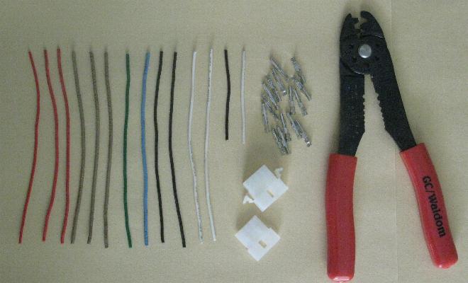
PARTS AND TOOLS NEEDED
1 - Switching power supply with +5VDC and +24VDC output
or - Switching power supply with +5VDC and +12VDC output
1 - 12 pin Molex Plug: 03-09-2122
1 - 4 pin Molex Plug: 03-09-2042
14 - .093" Female Pins: 02-09-1119
16-18 gauge wire of various colors
crimping tool for Molex pins
CONSTRUCTION (click on all following pictures below to enlarge them)
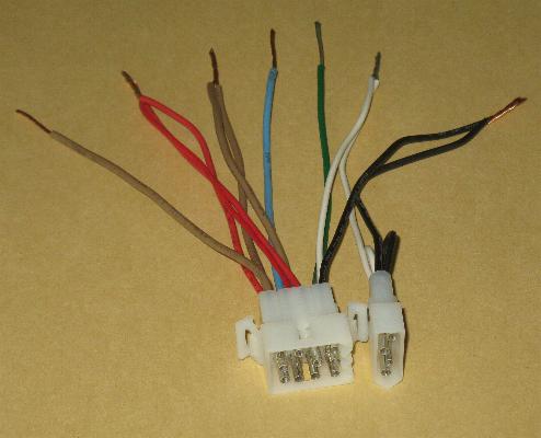
Cut 12 wires to 5" long (3-red, 3-brown, 1-green, 1-blue, 2-black, 2-white)
Cut 2 wires to 2.5" long (1-black, 1-white)
Attach the pins. Take note of how the 2.5" wires are attached.
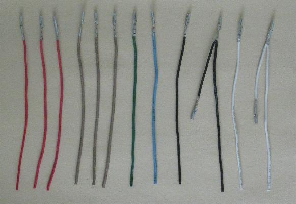
Wire the 4 pin Molex connector. Insert the pins until a click is heard.
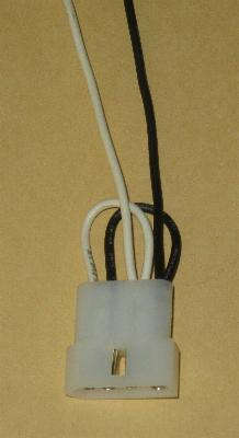
Wire the 12 pin Molex connector. Back row first. Take note of the triangle "keys" in the bottom front.
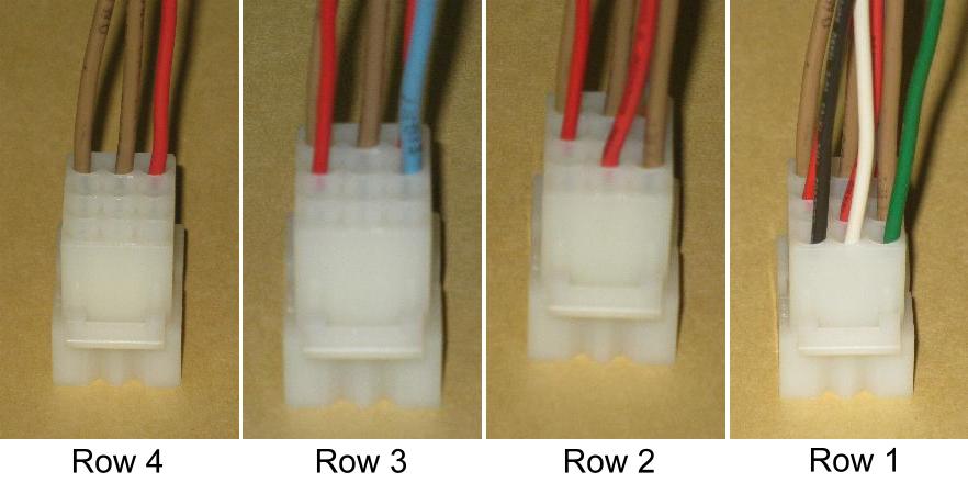
Strip the wire ends and twist them together as shown.
The two "GND" terminals are the same, so the brown wires can be attached in any combination.
Attach to the Power Supply. (The blue wire can be attached to either +24V or +12V)
Some power supplies will have negative voltages (-5V or -12), never attach to these, it will damage your board.
 or
or 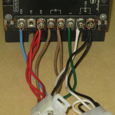
That's it! Mount the new power supply. Attach the main harness.
Enjoy the game!
DISCLAIMER OF LIABILITY
We are dealing with raw power here, which can be very dangerous to yourself and to your machine. Improper wiring CAN and WILL damage your circuit boards. This document is presented for reading enjoyment only. If you proceed to modify your equipment, your are doing so at your own risk and you accept full and sole responsibility for the results. The Dragon's Lair Project makes no warranty or assumes any legal liability or responsibility for the accuracy, completeness, or usefulness of any information, apparatus, product, or process found in this document.
QUESTIONS? COMMENTS?
PROBLEMS?
Contact Us
HOME
| LASER GAMES |
LASER COMMUNITY
| TECH CENTER
This website was created by
Jeff Kinder
& Dave Hallock, 1997 - 2024.
All trademarks and copyrighted materials are property of their respective
owners.